CDP Visualization Model for Software Requirements
- Daksh Gupta

- Jan 16, 2025
- 6 min read
Updated: Jan 17, 2025

According to all statistics, SCRUM is among the most popular frameworks for Agile Software Development. It includes the idea of Product and Sprint backlogs, which consist of a prioritized list of software requirements written in the text format and one of the most commonly used text formats is known as "User Stories".
If you’re using SCRUM and maintaining a backlog in the form of user stories, then here is what you must know
User Stories are not part of SCRUM. It was created by eXtreme Programming (XP). SCRUM doesn’t recommend or mandates using User Stories or any specific way of representing the Backlog.
A Disclaimer on User Stories
My intention of this post is not to say that User Stories are bad, instead what I’m trying to explain is that there is a visual way of representing things which are more suited for software development of the day.
There is no harm in using User Stories if it serves the purpose or clearly explaining the end user requirements.
A Picture is worth Thousand Words
Research after research it’s proven that the a picture is indeed worth thousand words and the chances for humans to understand and comprehend something with pictures increases drastically

Software requirements often face challenges related to understanding and interpretation, particularly with brief text-based descriptions, which can be significantly reduced through visualization.
But we’re not doing it…!!! Why?
One reason could be that we lacked a universal, straightforward method to describe the requirements... But that was true only until now.
Introducing CDP
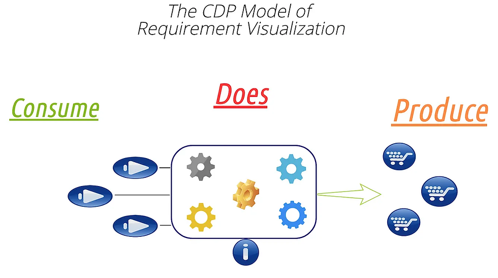
Let me introduce you to CDP (Consume → Does → Produce) Model of visually describing the software requirements.

This model is actually derived from well known IPO (Input → Process → Output ) model of software development, but changed to ( Consume → Does → Produce) to better reflect the nature, characteristics and complexities of software requirements.
So What exactly is CDP ?
CDP stands for : Consume → Does → Produce
All software is designed to perform specific tasks, whether it's as simple as adding two numbers or making a web request to stream a movie. Like anything else, software cannot operate without input and it must also product the output of the actions performed.
In case of summing two numbers, it needs numbers. To stream a movie, it needs the URL of streaming service, name , languages etc.
The working of the software is determined by the output it generates. Therefore, with Produce, we fulfill the intended purpose of the requirement.
The primary benefit of a Visual reference model is its ability to convey information to both software developers and stakeholders with minimal differences in both interpretations.
Here is how the generic CDP visualization shall look like
Okay, let’s see the same with some Examples
Let’s assume that you need to build your house. Here is how you’ll write the same in the form of a text based user story
As a house owner, I want to build my house, so that I can live in that
And here is how it will be represented visually using CDP model

The obvious and main difference is that in user stories, we can’t specify what all we want to get this done
What looks better ?
I’ll leave the answer to you, but here are a few specific things I’d like to mention
The CDP (Consume → Does → Produce) Clearly explains what will be CONSUMED and what will bePRODUCED as part of the work.
The DOES part can be a Grey box because it depicts WHAT and not HOW part where the development expertise kicks in to do the things in a better way.
The biggest advantage of Consume → Does → Produce is a visual requirement mapping from top to bottom and their relationships which is intuitive and understandable.

How to generate smaller requirements from a bigger one?
It’s possible to create a hierarchy of requirements based by breaking a big requirement into smaller ones.
To better understand the same, let’s continue with our example of breaking the requirements of building the house using CDP, let’s break the building construction into two separate smaller requirements
Building walls & CeilingS
Painting
Here is how it can be depicted in the CDP Model

Here, we can not only connect the placement of requirements and comprehend their necessity, but we can also negotiate two entirely separate contracts: one for Building Walls and Ceiling and another for Painting. The dependencies are also very clear.
Not only that, a visual reference can very well tell what we can expect from the completion of a particular requirement.
If this visual reference model doesn't appeal to you, feel free to skip the remainder of the post :) as I'll be explaining the same concept using a real-world software example involving the creation of a cloud based micro-service(s).
Describing the requirement of Building a Micro-Service using CDP
Problem Statement:-
We have to build a Micro-Service (Let’s call it Date-Time Service) which tells the user about current data and time?
Let’s try depicting this requirements first by writing the same using text based user stories, which may look something like
As a Microservice, I want to provide current date and time so that system components can set the correct date and time
Now, Let’s see how it will look like with CDP based representation
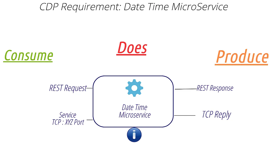
Aren’t the requirement looks absolutely clear? (Yes/No)
By no means text based user stories can indicated so much details about the requirements in a simple picture like
How the Date Time MicroService shall be contacted (What it Consumes?)
How shall it responds to the request (What it Produces?)
And of course What it Does?
Not only this, if the requirement changes later on, It’s extremely easy to identify what is changing.
For example, If we decided to add GraphQL support in Date Time Microservice, we can depict the same easily just adding some color codes as depicted below
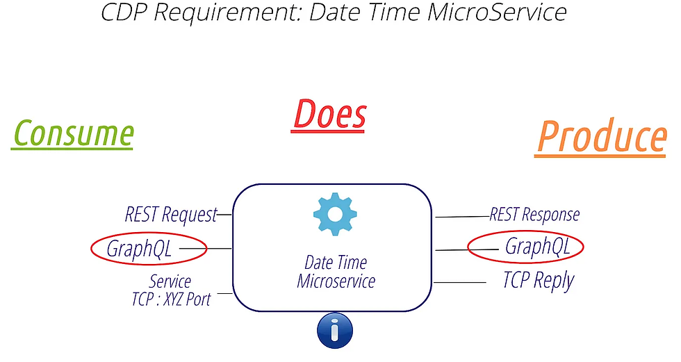
Unlike user stories, we’re not writing a new requirement, but adding additional info to the existing requirement which correctly depicts what additional things need to be done
Breaking the Microservice requirement into multiple smaller requirements
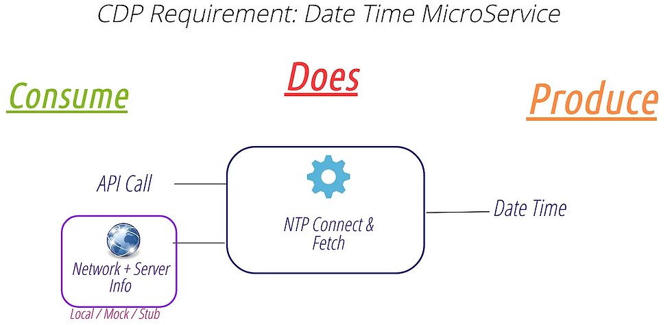
Similar to constructing a house, it's straightforward and intuitive to divide microservice requirements into several smaller ones. However, for the sake of simplicity, I will discuss just one internal requirement, which is as follows:
To know the current Date and Time, the microservice needs to connect to an NTP (Network Time Protocol) Server and here is how the CDP requirement model for the same shall look like

Something truly awesome about Consume → Does → Produce model
Imagine a scenario where the team implementing the NTP Connect & Fetch requirement doesn’t have Network & Server Info available at the time of development.
Things like this happens all the time during normal development, isn’t it?
So the team decides to either use local NTP Server or Mock or Stub out the same which allows them to complete all the complex functionalities, but they will have to come back later when the actual NTP server is available for testing the requirement.
Here is how it can be depicted in the CDP model
Now anyone who sees this requirement knows that the implementation as of now contains the mocked server and shall need to be removed later on. At a later point of time, when this requirement is picked up again, it will be only to remove the mocking / local server work around.
If I just talk about the transition of requirement, it will look like

The greatest advantage of the CDP model is that it not only illustrates the flow of implementations in relation to the requirements but also clearly demonstrates what is being done for both developers and stakeholders.
Consider handling these requirements with text based user stories, how easy of difficult will it be?
Try using this model and see if it works for you
If you want to know more or need some help in implementing this visual requirement model. Please do reach out to me.
Thanks for reading..
Daksh


Comments